2022-06-21
Mars in 3D! Digital Terrain Model Update #1
By Christian Tate, Roland K. Aristide, and the Mastcam-Z Team
[NOTE: This is the first in a series of blog entries by Mastcam-Z team members who are focusing on creating DTMs – Digital Terrain Models – of the Martian surface in Jezero crater based on Mastcam-Z stereo images. These DTMs are being created for both scientific analysis as well as public outreach/educational use.]
As the Mars2020 Perseverance Rover team prepares to collect the next sets of samples from the Jezero delta, this first “Mars in 3D!” article looks back – in high-res 3D – at the first-ever successful rock sample collected from Mars.
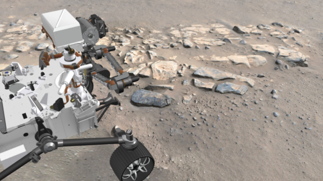
The first two successful sample cores, Montagnac and Montdenier, were collected from a rock identified by the name Rochette located along the boundary of two geological units in Jezero crater (Figure 1). These samples are a crucial part of the Mars Sample Return (MSR) mission, which will transport Martian rock samples to Earth over the course of a multi-mission campaign, providing both a scientific bonanza as well as a testament to humanity’s technological advancement and determination.
Rochette stands on Citadelle ridge south of the Octavia E. Butler landing site. The Mars 2020 science team chose this location for its position in the “crater floor fractured rough” geological unit (abbreviated Cf-Fr) near its border with Séítah.
The data in Model 1 below provide an interactive tour of Rochette and its surroundings. Click the play button on the figure window to start the 3D experience and navigate or free-roam through labeled areas of the site. We put several markers on the model to some of its important features. (Tip: Double click anywhere on the model to recenter the view.) Accompanying the model, a black and white scale bar provides viewers with an indication of the model’s scale size and orientation, denoted by its north facing arrow. For an enhanced navigation experience, view the model in full-screen mode!
Model 1: The first sampled rock, Rochette, in the context of the Citadelle site, sol 180. Photo credit: NASA/JPL-Caltech/ASU/MSSS/Cornell.
The first view is Rochette from the perspective of Perseverance looking southeast (annotation 1). Navigate around the Citadelle model and especially notice how a black scale and compass indicates which direction is north (annotation 2). Once acquainted with Citadelle, zoom out and notice how the northeast side of the model is lower in elevation than the rest. This ridge is a layer of rocks similar to Rochette that sits atop Séítah, the sandy region to the north. Tire tracks are even visible from where Perseverance climbed through a break in the ridge, turned, and entered Citadelle. There are two other rows of light-toned rocks parallel to the ridge; these are three planar layers that slope towards the Southwest. Rochette belongs to the middle of these three layers in the Cf-fr unit.
Rochette’s uniqueness lies in its role as a representative of the large volume of rock in and around Citadelle. Mars 2020 scientists were drawn to the rock as a valuable site due to its ordinary and easily-accessible location. Though Rochette may appear bluer than its surrounding tan colored rocks, a closer look shows this simply comes as a result of wind keeping it cleaner than most of its neighbors despite being a part of the same rock family.
Model 2 displays a zoomed-in, high-resolution model of Rochette before Perseverance disturbed the rock and its surrounding sand. Several changes occur on and around Rochette after the force and vibration of the abrasion process.
Model 2: Rochette pre-abrasion, sol 180. Photo credit: NASA/JPL-Caltech/ASU/MSSS/Cornell.
Model 3 shows Rochette after Perseverence’s abrasion tool gouged a smooth 5 cm circular patch on its surface facing Perseverance, identified as the Bellegarde abrasion. This preparation is necessary for the sensitive measurements that PIXL and SHERLOC make of the rock’s chemical composition. Notice first the pile of gray powder below the abrasion patch. These are the cuttings from the abrasion tool. Comparing closely the two pre-abrasion and post-abrasion models, pebble-sized rock fragments that chipped off of Rochette become visible; however, these are not not the pieces of debris dislodged from Rochette. Notice also the rust-red powder on its right,Southwest side. There is also a small cave-in of the sand behind the rock. These features become more evident after the more violent process of coring Rochette.
Model 3: Rochette post-abrasion, sol 185. Photo credit: NASA/JPL-Caltech/ASU/MSSS/Cornell.
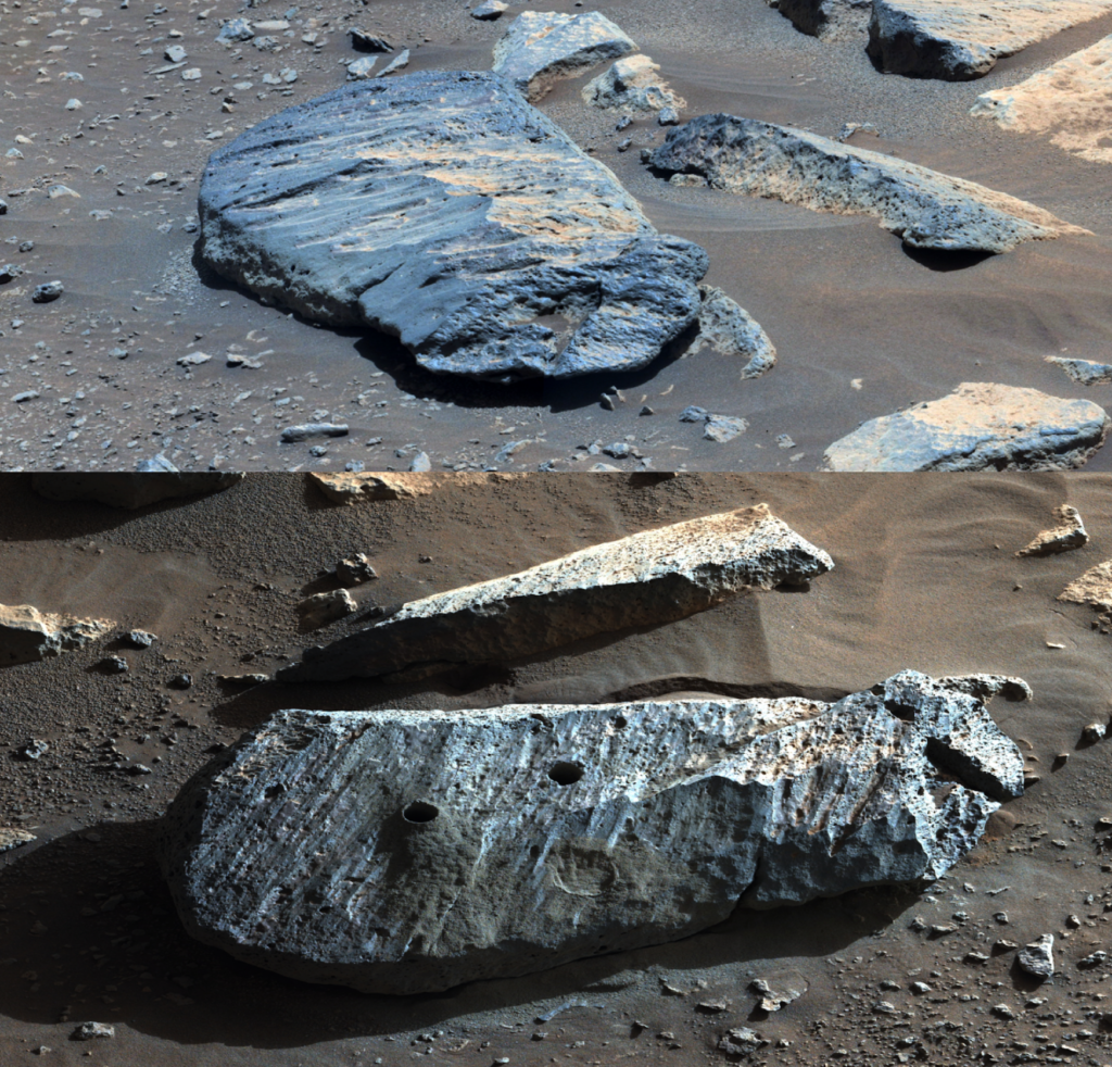
Model 4 displays Rochette after all the banging and rattling needed to drill 7 cm into the rock and extract 1.7 cm diameter cores at two locations had ceased. The two cores, named Montagnac (first, south side) and Montdenier (second, north side), are now sealed in tubes and stored within Perseverance itself. Notice how the coring process produced much more tailings and rock fragments than the abrasion process in addition to how it also distributed the material over most of Rochette, including the abrasion patch. The sand behind/southwest Rochette is also much more disrupted. A closer look on the south side shows many fine stress cracks in the sand’s rigid crust.
Model 4: Rochette post-coring, sol 195. Photo credit: NASA/JPL-Caltech/ASU/MSSS/Cornell.
The lighting pattern on the post-coring model appears different as a result of the images being taken in the evening as the Perseverance team was eager to get the rover on its way to explore its next stop in Séítah after finishing its work at Rochette.
Although these core samples for the Mars Sample Return Mission likely won’t arrive at their new home on Earth until the early 2030s, these 3D models of their host rock bring us closer to understanding where they came from. We created these models with stereo Mastcam-Z images alongside a photogrammetry process called Structure from Motion (or SfM). SfM compiles several images taken from different angles of the same scene and semi-automatically produces a 3D product. Software applications for SfM, such as Agisoft Metashape which we use for these models, are readily available and continue to grow in performance and accessibility. SfM models have grown in popularity through 3D modeling communities, like Skechfab – the social media viewer and repository for 3D models used in the above models, making it easier for developers to share their work with all.
To learn more about how we see Mars, the extraction of samples, 3D modeling the martian terrain, and how you can view images and data directly from the Perseverance Rover, please visit our own Mastcam-Z blog to browse a wide collection of news and updates!